- Home
- About Us
- Products
- Applications
- Support
- Blog
- Home
- About Us
- Products
- Applications
- Support
- Blog
Vacuum Metal Etcher

- Benefits
- Operation
- Pump Module
- Theory of Vacuum Metal Etching
Benefits
- Fully automated batch process
- Fast throughput
- Eliminates “snow” and “bridging”
- High yield
- End point detection
Operation
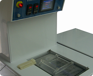
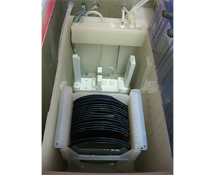
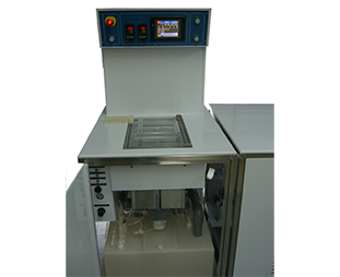
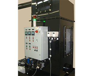
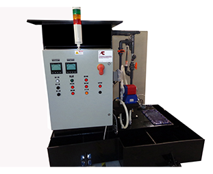
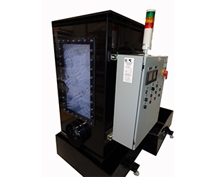
Place one or two standard cassettes in the etch process tank. One wafer is operator-selected and placed in the Endpoint Detector Assembly.
The user programs Etch/Over etch mode and Rinse Times. In Ready mode, Cycle Start switch evacuates the plenum which draws acid up from the reservoir into the etch tank. The Etch Tank Level switch closes the acid transfer valves and the etch cycle begins.
Etching continues until the etch time elapses or the Endpoint Detector senses that lines have been etched through the aluminum layer, and over etch time comes into effect to further define the circuit geometries.
Over etch time is programmed as either fixed time or a percentage of the Endpoint Detector time frame.
At the end of the total etching period the plenum is vented to atmosphere and the transfer valves open to drain the acid to the acid reservoir.
Nozzles in the etch tank then spray DI water onto the wafer. DI water is used in the quench rinse and the final overflow rinse period cycle.
The end of the cycle is signaled by an audible alarm which can be operator-cancelled with the Reset switch. Reset causes the DI water to drain, after which the cassettes can be removed. The spray nozzles are then N2 purged and the system is ready for the next process cycle.


Pump Module
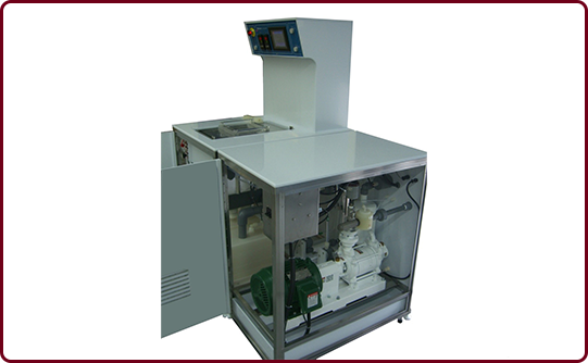
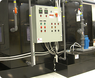
Housed in a separate module, the vacuum pump and controls are sequenced from the etch module. The water ring type vacuum pump requires minimal maintenance and is ideally suited for pumping hazardous and corrosive gases.
The pump is supplied with a continuous flow of city water which passes through two stages and encapsulates gases, preventing damage to the internal parts of the pump.
A separator on the discharge port extracts the gases and drains the water. A flow switch on the water input line cuts off the pump if the supply is . insufficient. A non-return valve on the vacuum port prevents back-siphoning of city water to the etch module if the pump stops.


Theory
It has been proven that to etch aluminum wafers with a vacuum etcher will eliminate the “snow” formation and reduce metal line width loss.
To eliminate the “snow” is difficult if the wafers are etched in hot bath. The “snow” comes from the hydrogen bubble which is generated in the chemical reaction during the etching process adhered on wafer surface to block the continual chemical reaction to leave the aluminum residue — “snow”. These bubbles will not release unless there is a force enough to break the surface tension, (such as the agitations in the etching which creates a friction to remove the bubble). The “snow” can be removed by using a longer over etch time, but the narrower metal line width will occur. The vacuum etcher is designed to solve this problem.
The narrow metal spacing and the areas which contain the higher steps are easy to hide the “snow”. We have extra difficulties to etch (2-3u thick metal) and (10u pitch negative resist) and some (narrow pitch) wafers. The “etch-bake-etch” process can solve some problems but does not have too much help on wafers due to the metal step too high to cover the entire aluminum side wall by melted resist in flow bake.
The feature of the vacuum etcher is that the aluminum wafers are etched in a vacuumed chamber. The hydrogen bubbles that releasing are so rapidly from the wafer surface in the low pressure environment (20 torr) during the etching because the surface tension is highly reduced in this condition. The infrared endpoint detection allows the process to optimize the over etch time to minimize the metal line.


- Benefits
- Operation
Benefits
- Fully automated batch process
- Fast throughput
- Eliminates “snow” and “bridging”
- High yield
- End point detection


Operation
Place one or two standard cassettes in the etch process tank. One wafer is operator-selected and placed in the Endpoint Detector Assembly.
The user programs Etch/Over etch mode and Rinse Times. In Ready mode, Cycle Start switch evacuates the plenum which draws acid up from the reservoir into the etch tank. The Etch Tank Level switch closes the acid transfer valves and the etch cycle begins.
Etching continues until the etch time elapses or the Endpoint Detector senses that lines have been etched through the aluminum layer, and over etch time comes into effect to further define the circuit geometries.
Over etch time is programmed as either fixed time or a percentage of the Endpoint Detector time frame.
At the end of the total etching period the plenum is vented to atmosphere and the transfer valves open to drain the acid to the acid reservoir.
Nozzles in the etch tank then spray DI water onto the wafer. DI water is used in the quench rinse and the final overflow rinse period cycle.
The end of the cycle is signaled by an audible alarm which can be operator-cancelled with the Reset switch. Reset causes the DI water to drain, after which the cassettes can be removed. The spray nozzles are then N2 purged and the system is ready for the next process cycle.


- Pump Module
- Theory Of Vaccum Metal Etching
Theory
It has been proven that to etch aluminum wafers with a vacuum etcher will eliminate the “snow” formation and reduce metal line width loss.
To eliminate the “snow” is difficult if the wafers are etched in hot bath. The “snow” comes from the hydrogen bubble which is generated in the chemical reaction during the etching process adhered on wafer surface to block the continual chemical reaction to leave the aluminum residue — “snow”. These bubbles will not release unless there is a force enough to break the surface tension, (such as the agitations in the etching which creates a friction to remove the bubble). The “snow” can be removed by using a longer over etch time, but the narrower metal line width will occur. The vacuum etcher is designed to solve this problem.
The narrow metal spacing and the areas which contain the higher steps are easy to hide the “snow”. We have extra difficulties to etch (2-3u thick metal) and (10u pitch negative resist) and some (narrow pitch) wafers. The “etch-bake-etch” process can solve some problems but does not have too much help on wafers due to the metal step too high to cover the entire aluminum side wall by melted resist in flow bake.
The feature of the vacuum etcher is that the aluminum wafers are etched in a vacuumed chamber. The hydrogen bubbles that releasing are so rapidly from the wafer surface in the low pressure environment (20 torr) during the etching because the surface tension is highly reduced in this condition. The infrared endpoint detection allows the process to optimize the over etch time to minimize the metal line.


Applications
- Wet processing stations
- Tech benches
- Fume hoods
- Plating station
- Precision cleaning stations
- Acid exhaust hoods
Benefits
- Fully automated batch process
- Fast throughput
- Eliminates “snow” and “bridging”
- High yield
- End point detection


Operation
Place one or two standard cassettes in the etch process tank. One wafer is operator-selected and placed in the Endpoint Detector Assembly.
The user programs Etch/Over etch mode and Rinse Times. In Ready mode, Cycle Start switch evacuates the plenum which draws acid up from the reservoir into the etch tank. The Etch Tank Level switch closes the acid transfer valves and the etch cycle begins.
Etching continues until the etch time elapses or the Endpoint Detector senses that lines have been etched through the aluminum layer, and over etch time comes into effect to further define the circuit geometries.
Over etch time is programmed as either fixed time or a percentage of the Endpoint Detector time frame.
At the end of the total etching period the plenum is vented to atmosphere and the transfer valves open to drain the acid to the acid reservoir.
Nozzles in the etch tank then spray DI water onto the wafer. DI water is used in the quench rinse and the final overflow rinse period cycle.
The end of the cycle is signaled by an audible alarm which can be operator-cancelled with the Reset switch. Reset causes the DI water to drain, after which the cassettes can be removed. The spray nozzles are then N2 purged and the system is ready for the next process cycle.


Pump Module
Housed in a separate module, the vacuum pump and controls are sequenced from the etch module. The water ring type vacuum pump requires minimal maintenance and is ideally suited for pumping hazardous and corrosive gases.
The pump is supplied with a continuous flow of city water which passes through two stages and encapsulates gases, preventing damage to the internal parts of the pump.
A separator on the discharge port extracts the gases and drains the water. A flow switch on the water input line cuts off the pump if the supply is . insufficient. A non-return valve on the vacuum port prevents back-siphoning of city water to the etch module if the pump stops.


Theory
It has been proven that to etch aluminum wafers with a vacuum etcher will eliminate the “snow” formation and reduce metal line width loss.
To eliminate the “snow” is difficult if the wafers are etched in hot bath. The “snow” comes from the hydrogen bubble which is generated in the chemical reaction during the etching process adhered on wafer surface to block the continual chemical reaction to leave the aluminum residue — “snow”. These bubbles will not release unless there is a force enough to break the surface tension, (such as the agitations in the etching which creates a friction to remove the bubble). The “snow” can be removed by using a longer over etch time, but the narrower metal line width will occur. The vacuum etcher is designed to solve this problem.
The narrow metal spacing and the areas which contain the higher steps are easy to hide the “snow”. We have extra difficulties to etch (2-3u thick metal) and (10u pitch negative resist) and some (narrow pitch) wafers. The “etch-bake-etch” process can solve some problems but does not have too much help on wafers due to the metal step too high to cover the entire aluminum side wall by melted resist in flow bake.
The feature of the vacuum etcher is that the aluminum wafers are etched in a vacuumed chamber. The hydrogen bubbles that releasing are so rapidly from the wafer surface in the low pressure environment (20 torr) during the etching because the surface tension is highly reduced in this condition. The infrared endpoint detection allows the process to optimize the over etch time to minimize the metal line.


Contact us if you need more information about using our Vacuum Metal Etcher system.
